FreeCAD: pad,extrusions and sketches detachment from objects and positioning
fr/de/it
While modelling the Class 43 IC 125 HST locomotive I decided to create an object data base as modular as possible: three basic objects (the cabin, the body, the back end), each of them in multiple, different version. I started with the basic full shape, then I added the cuts for the windows, the cuts for the grids, and finally the handrails and roof details.
My goal was to have a set of reusable single objects that I could plug in a new data base (a so called “project” in FreeCAD) in order to create:
- different versions of the locomotive (e.g. with or without back side window),
- the same locomotive with varying level of details for different modeling kits, and
- the model of the Mk3 coaches that go together with the locomotive
to haveand make up the complete trainset.
As the workbenches in FreeCAD are not meant exactly for this approach, the creation of my 3D objects data base was not straightforward: I had to find some tricks and workarounds.
I already faced some challenging issues related to the positioning and orientation of pads and extrusions, as well as the detachment of sketches from surfaces and their repositioning: the front window of the cabin, the right side window of the back, the side windows of the body.
The front window
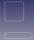 Starting from the blueprint I created the sketch of half of the front projection of the windscreen and the front lights housing . The front of the cabin
 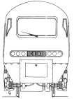 has two main slopes where these cutouts will be made, along the longitudinal axis of the train, which is not
 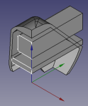 perpendicular to the external sloping surface. I placed the sketch at the origin of the axes, oriented it on the xz plane, created a pad long enough to intersect completely the front slopes of the cabin and cut them out from the cabin shape.
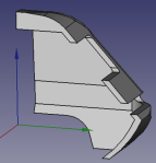 Then I wanted to add a the frame to be placed inside the window cut, representing the rubber seal in the real case, where the modeler can glue the film representing the window glass. The final object is a solid with a rectangular section, running around the window borders, at some distance from the front surface, lying on the surface of the cut through section plane (i.e. the xy plane, which is not perpendicular to the front face of the cabin). I created
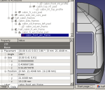 a sketch attached on the front face of the cabin, I drew the border of the frame extracting the borders of the cut as external geometry references, then I created an extrusion and I positioned it slightly backward with respect to the front surface. I added a fillet on the spicky front corner. I did similarly for the side window frames. In these cases, the sketch remains attached to the surface I used as reference, the positioning of the frame extrusions is relative to it.
The back side window
The side window is mainly (but not completely) a cut through a face which is rotated with respect to the central part of the back of the coach, where the door is placed (with a window cut along the y axis), perpendicular to the face it is cutting. It is straightforward to do it using the “Pocket” feature of the “Part Design” workbench, but I needed to keep separated the original uncut object (for versions of the train without this window) and the pad like object (created as an extrusion of the shape of the cut) to cut through the window for the versions I need: I wanted to have the final cut as a result of a “cut” boolean operation of the “Part” workbench. The challenge in this case was to find the parameters of the direction perpendicular to this rotated face, to be used for the direction of the extrusion. Studying the 3D geometry math behind the python code of FreeCAD would be a very interesting task, which I keep on the shelf for later, when I will need to code some new features to enhance the tool. I found, instead, the workaround using the GUI: I duplicated the sketch attached to the face I used for the cut. The duplicate is also attached and, of course, sharing the same positioning and orientation parameters. I select the menu item “reorient sketch”, which pops up the question “do you want to detach it?” , I click on “yes”. By the way: this is an easy way to create a sketch positioned and oriented to match a face, without having it attached: after detaching, it’s enough to click on “cancel”: the detachment takes place anyway, without reorienting the sketch. In my case I also reoriented it on the xy plane, automatically setting to 0 all the positioning and orientation parameters. I created an extrusion along the z axis (thus perpendicular to the sketch) which is relative to the “0” coordinates of the xy plane.  Then I repositioned the extrusion, copying the parameter values of the original sketch attached to the face to be cut (which I kept for this purpose) into the “data” properties tab of the extrusion, positioning and orienting it exactly where the cut was needed, moving it slightly away (but still parallel) from the surface, else the result of the cut keeps the surface uncut where the extrusion starts, lying on the surface to be cut. Then the cut boolean operation was possible.
The side cuts of the body
In the first version I just created a sketch on the yz plane, then created a pad thick enough to cut reach out of the body and then cut one shape out of the other: neat enough for my data base organization and good enough for the orientation of the window cuts and the frames: as the slope of the side of the body is not so distant from the vertical, the x axis is an enough good approximation for the naked eye of the perpendicular to the external surface of the train. Being extremely self-demanding about quality and precision, wanting to show the details of the 3D model to potential customers (small scale train modelers are very keen on small details) and foreseeing cases where the slope of a surface would be anywhere in the 3D space, I went for the optimized precision-vs-data base reusability version.
I created the reference sketch for the cuts, as usual, on the xy plane. I attached a duplicate of the sketch on the internal side face of the body (it is parallel to the external one by construction) and used it to cut a Pocket (a hole) through the body. I created the internal frame sketch on the xy axis, and extruded it along the z axis. The positioning required a “cut and paste” hand workaround: it had to be oriented as the side face of the body, pushed 0.3 mm away from the internal face of the train. I created a dummy sketch attached to the lower face of the window cut where I drew a 0.3 mm line, 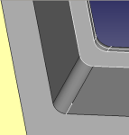 exactly on the border of the flat part (where the corner rounding starts, it can be extracted as construction geometry from the face you attach the sketch on). I copied and pasted the rotation parameters from the sketch I used for cuts (attached to the internal face of the body), then I selected the vertex of the dummy 0.3mm long line, I wrote down on paper it’s coordinates from the frame of the GUI (being fast: they disappear a few seconds after selection), I did the same for the corresponding vertex of the frame (properly oriented, but needing to be traslated), calculated the differences in the corresponding coordinates and added them to the positioning parameters of the frame. The need to writ a script in Python to do this automatically is becoming more urgent 😉
…to be continued
Back to the top of page.
Le Titre
en/de/it
Cet est le text.
Retour en haut de page.
Der Titel
en/fr/it
Das ist das Text.
Zurück nach oben.
dimensioni svg vs dimensioni in Inkscape e FreeCAD
en/fr/de
Ritorno all’inizio della pagina.