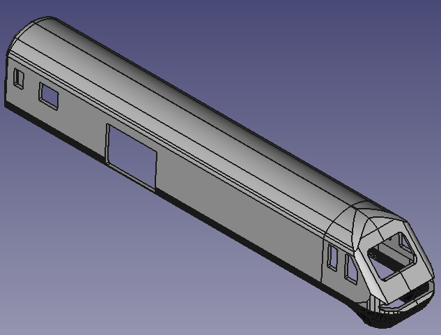
Here it is: the cabin with all the details, including the lower valance panel borders. 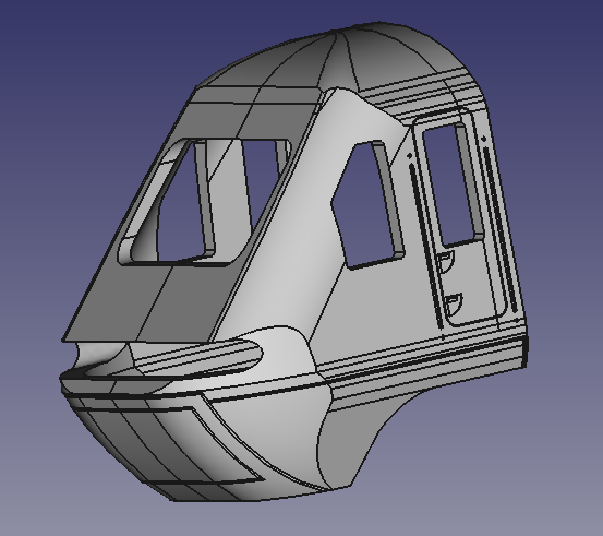
…already printed in two different resins
Here it is: the cabin with all the details, including the lower valance panel borders.
…already printed in two different resins
The upper cabin is re-extruded, using the newly made lower valance top profile.
The shape is fine up to the real top dome: the diagonal ridge must be removed.
I decided to keep only the lower bulk of the cabin, cutting out the really curved top and the back straight part. This allowed me to focus on the top curved shape.
I realized it intersecting two parts of ellipsoids. The ridge at their intersection can be easily smoothed with the “fillet” tool of FreeCAD.


 This cap extends below the top of the cabin bulk, only the upper part is kept: a solid, shaped as a pyramid, with the faces sloping tangentially to the uppermost section of the bulk, is used to cut out the top cap.
The top and the bulk are properly matching at the sides. Extending the back face of both, the cabin shape is complete: only the spiky edge at the front of the bulk must be smoothed. This is easily done, cutting out the edge with a huge cone.


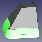
In the resulting shape there is no more mismatch between the top cap and the bulk. A fillet with a big radius on the cone-cutout right edge (in green in the picture), gives then the final shape. The back of the upper cabin is backwards extended horizontally to the required full length of the cabin.


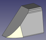
The basic lower valance is too prominent in the upper curved profile and too spiky in the lower part: a round cutout of the shape is needed. The right curve is created with an eight of an ellipsoid, placed and shaped with a fine tuning to match exactly the needed curve as well as the remaining parts of the basic shape.
The front part of the valance is then created extruding the side face of the ellipsoid, while the back side part of the basic valance is kept. With a little work of extrusion and boolean operations, the final lower valance full shape is there.


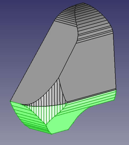
For the final cabin, an empty shape is needed, with a given thickness. It’s enough to clone (in green in the picture) the full shape, place it backwards and inwards of a distance equal to the needed thickness and cut it out from the original full shape.


Now the new top face of the lower valance must be extracted and used to make the upper cabin profile match the lower valance.
Time came to add the details to the class43 plain model. When trying to intersect one of the details with the lower valance, imported as stl object, the troubles came: FreeCAD doesn’t support stl proper handling and it was not really possible to do boolean operations between FreeCAD objects and and stl import. Perfectionist as I am, as well as my modelling partner is 😉 , I took the chance to re-think the cabin as a complete FreeCAD project. The basic shape is still created intersecting the extrusions of the three orthogonal profiles, this time created with Inkscape from the blueprint and imported directly into FreeCAD in svg format.


The cabin is again split into two parts: the upper part and the lower valance.
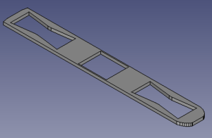
To be complete, I added two “bridges” over the cutouts for the bogies, to hang them and I designed the case for the engine, to be hosted in the chassis.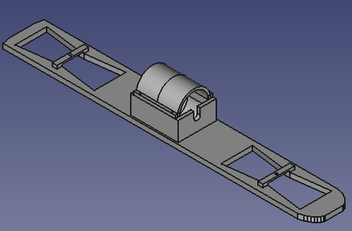
The engine case is shaped to host the engine inside it and the cover designed to be fastened by screws to it.


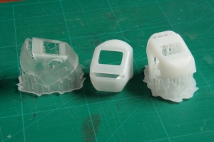
The class 43 cabin right out from the printer: in the picture in the middle of the right column it is next to the first print I made at Shapeways (the public transportation card placed below -“credit card” format- is just as reference for the size), while the two on the bottom right show the piece with the support structure generated by the printer, then easily removed with a clipper. Both the upper part and the lower valance are much more “curved” and close to the original than in the first model.


The outline of the chassis must match the open bottom line of the model. Being the model symmetrical with respect to the longitudinal axis, it’s enough to draw half of the outline, which is easily done by intersecting a plane with half of the locomotive model. For the cabin, only the lower valance is needed.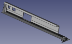
Once the section is available, some hand working with the “Draft” workbench is needed, 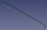 basically to downgrade the intersection object into lower level objects: first from a surface to a wire, then a wire into single edges. Once the edges are available, a wire closing the internal profile must be drawn, to be selected together with the the edges making the internal profile to be joined together again into a new “wire”object which will then be upgraded to a surface.
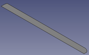 This is the outer surface to be then extruded and cut through for housing the engine and letting the bogies to be connected (the whole object being mirrored to have it complete).
The class 43 redesign is finished and ready for the 3D printer.
It’s the right time to test the brand new printer at home, let’s print the cabin in white resin, with the highest precision available. Just started… it will take three hours, it will be ready after lunch 😉 .
 The cabin basic design, still
  needs to be rounded on the spiky side edge and smoothed on the top, before proceeding to the fine filing. It is easier to re-build the shape of only the upper part of the cabin inside FreeCAD: with just one simple “fillet” action on the side edge, the basic rounded shape is there.
Smoothing the ridge on the top is a little bit more tricky: applying a fillet to any short edge doesn’t work well, as the segments composing the ridge are oriented in different angles. Then the solution is to cut away the spiky part of the ridge, leaving a smoother surface instead.
I created a profile which was cutting out the ridge, but at the same time including the whole upper cabin. The solid generated revolving it around the longitudinal axis includes the cabin, cutting out just the thin part of the ridge to be removed. The boolean difference of the two shapes does the rest of the job: the result is the original cabin, with a smooth surface instead of the ridge.

This shape is now ready to have the windows cut out, before being exported in stl format to be finely adjusted inside Blender.
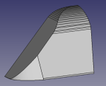
The lower valance Lorenzo designed with OpenSCAD shows a significant improvement compared to the original basic model I 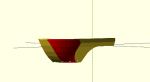 created with FreeCAD.
Nevertheless it remains too spiky and irregular in the inside profile. Here comes into play my skills as a new Blender user: I had 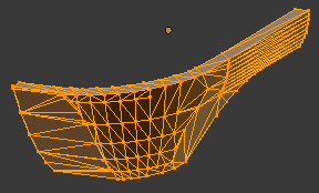 a lot of fun learning the basics of meshes manipulation to adjust, recreate and smoothen it.
Now it’s time to adjust the other profiles to this new refined lower valance and re-create the upper part of the cabin.
